The reason for the production of the part drawing in addition to the details that are included in it
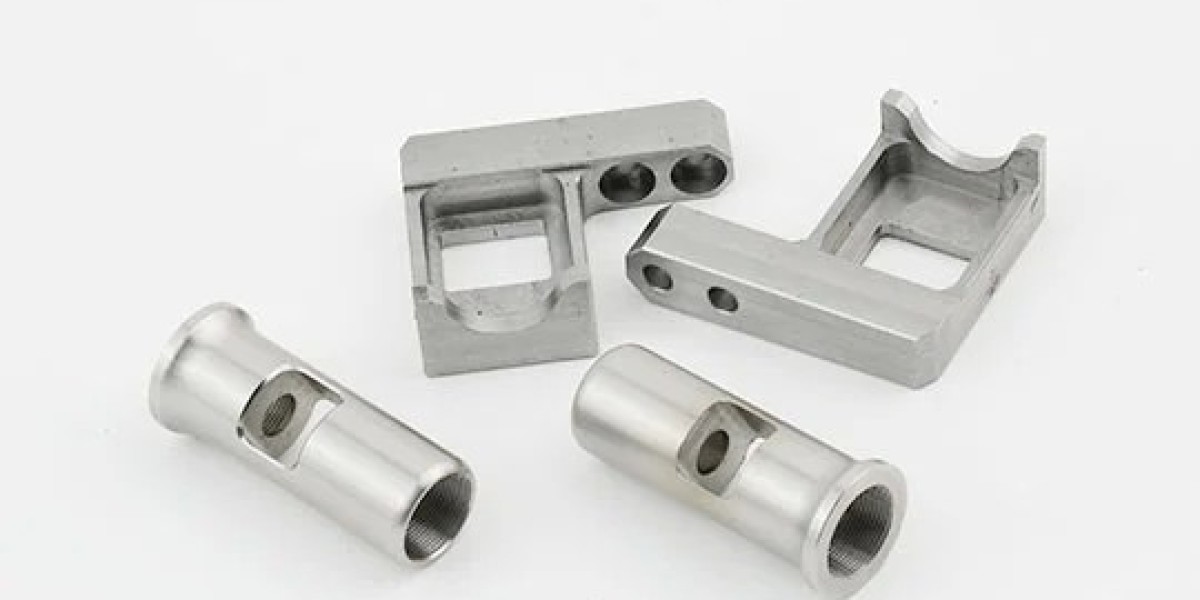
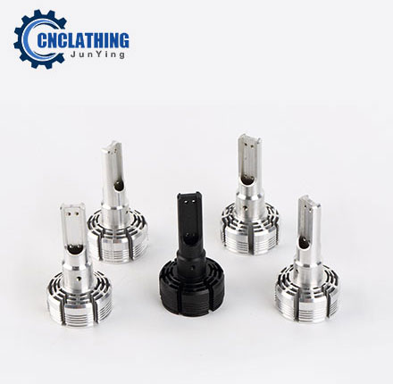
The production and testing of parts are grounded in the part working drawings that are used throughout the process. These drawings are created based on the position and function of the parts in the machine. This position and function determines, among other things, the requirements for the parts' shape, structure, size, materials, and other technical data.
Components such as a title bar, a collection of graphics, the required size, and specific technical requirements are what come together to form the part drawing.
Details for the technical drawing of the component's specifications
Tolerance and appropriateness
The elastic relationship that exists between the different components is referred to as "fit," and the term fits refers to this relationship.
<1>Dimensional tolerances
The value of the linear dimension as expressed in a particular unit is what the 1 Dimension indicator refers to when used in a sentence.
2 The size of the base; after applying the upper and lower deviations to this, compute the limit size.
A hole or shaft can be any size between its maximum and minimum dimensions. The larger dimension is referred to as the maximum limit size, and the smaller dimension is referred to as the minimum limit size. 4 Limit size: A hole or shaft can be any size between its maximum and minimum dimensions.
5 Size deviation: it has upper deviation and lower deviation, the maximum limit deviation minus the basic size will get the algebraic difference, which is called upper deviation; the minimum limit deviation minus the basic size will get the algebraic difference, which is called lower deviation; upper deviation and lower deviation are collectively referred to as limit deviation, and the deviation can be either positive or negative, or it can be 0. The limit deviation can also be 0.
⑥ Dimensional tolerance – Maximum limit size minus minimum limit size. It is a measure of how much of a difference in dimensions can be accommodated by a given size. Never lose sight of the silver lining when considering dimension tolerance.
Within the limit and fit diagram, there is a line that is called the 7 Zero line. This line is a straight line that depicts the basic size.
There are three markings to indicate proper assembly and tolerance.
1 The dimensional tolerances on the part drawing are broken down into three distinct categories.
Put a checkmark in the space next to the tolerance code.
Make a notation on the limit of the deviation.
The majority of the time, the assembly drawing will either mark the hole limit deviation value and the shaft limit deviation value separately or it will mark the linear dimension fit code.
The degree of abrasion on the surface
The micro-geometrical properties of the part's surface are referred to as the surface's roughness. Surface roughness is a term that refers to these properties. The terrain on these properties is broken up into a series of smaller hills and valleys.
There are three primary parameters of surface roughness that are specified by national standards. They are as follows:
The surface roughness is typically represented by the letter Ra, and the majority of the time this is the case.
Acquire a fundamental understanding of: To start, you should get yourself acquainted with the fundamentals of technical drawing by studying things like geometric shapes, different types of lines, dimensions, scales, and projections. Get yourself familiar with the necessary instruments, such as rulers, protractors, and compasses, and jot down any questions that come to mind as you do so.
Observe a consistent pattern: Devote a predetermined amount of time each week to the exercise of drawing technical diagrams. You can hone your abilities to draw lines, shapes, and measurements that are accurate and precise by starting with straightforward exercises and gradually progressing to more difficult ones as time goes on. As your skill improves, you should progress to drawing more difficult subjects.
You can educate yourself on the various approaches, conventions, and methodologies used in technical drawing by consulting online tutorials, textbooks, or other forms of instructional content. These resources can provide direction and demonstrations in a format that is straightforward and easy to follow step-by-step.